|
Here is a 3-way design that retains the focused sound of the MBOW1 above 500 Hz, but provides notably cleaner midbass production and, of course, deeper bass capability. The 3-way adds the Peerless 850146 CSC-X Line 10" woofer ($64 each at Madisound) in a two Cubic Ft. sealed box that can serve as a stand for an existing MBOW1. The bass-mid crossover is 350 Hz using a second order acoustic slope. MBOW1 owners can add the bass module with some fairly minor adjustments in the mid-tweeter crossover. The port should be stuffed with fiberglass or a similar material.
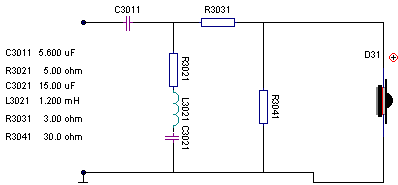
I have also developed a more economical version of the 3-way using the GR Research T2 1" silk dome tweeter. That will cut the parts cost by about $120. Substantial additional savings can be achieved by using a good quality NP Electrolytic capacitor (like Bennic) for the high uF values in the bass and mid circuits. With Bennic NP's, Axon poly caps in the lower value applications, Madisound 16 Ga air core inductors, and Eagle resistors, the entire parts cost of the "Econoline" version, with drivers, should be about $400, which would include some small value poly caps for bypassing the NP's. The bass and mid crossover circuits for the Econoline are identical to the MBOW1. The only change is in the tweeter circuit, which is provided below. The Econoline sounds very similar to the MBOW1. The highs seem to be a bit more focused forward, which is simply due to the narrower dispersion of the T2. The MBOW1 has a slightly more open, airy quality in the upper highs.
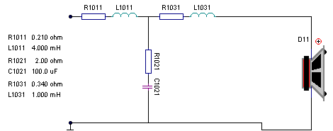
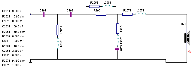
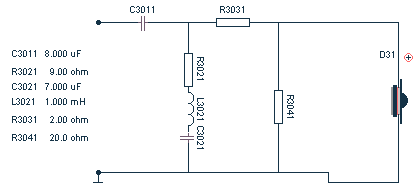
Here are the schematics for the crossovers. Note that the M130 is connected with REVERSE POLARITY. And as for all those little resistors with a value of less than 1 Ohm--they don't exist. That's just lspCAD's way of telling you the approximate dcr of the inductors.
NET 1 (Bass Low Pass Filter)
NET 2 (High Pass and Low Pass Filters for M130 Mid)
NET 3 (High Pass Filter for OW1)
Here is the revised tweeter circuit for the Econoline version using the GR T2 tweeter:
Changes Needed in an Existing MBOW1 Crossover
Net I (M130)
- Replace the first 1.25 mH series inductor with a 1.0 mH (or unwind the 1.25 if you can measure).
- Increase the 30 ohm bypass resistor to 50 ohms.
Net 2 (OW1)
- Increase the 6 ohm resistor in the shunt circuit to 9 ohms.
- Increase the 10 ohm resistor in the ground leg of the L-Pad to 20 ohms. (But you may want to choose an intermediate value, such as 15 Ohms, depending on your room acoustics and listening tastes. This will shelve the highs down slightly.)
Response Curves
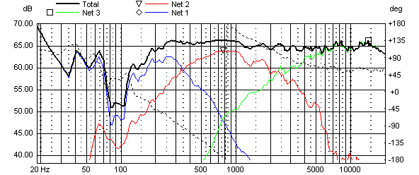
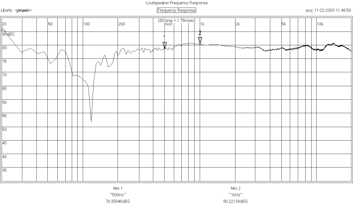
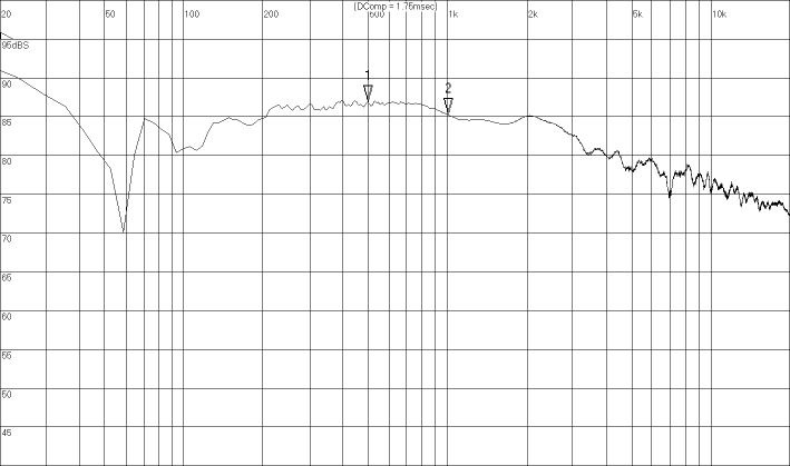
Here is the on-axis response predicted by lspCAD for a listening distance of about 12 feet, followed by the actual measured 1-meter response. They are quite close, and would be closer if it were possible to measure at a normal listening distance.
Predicted on-axis response
Measured on-axis response
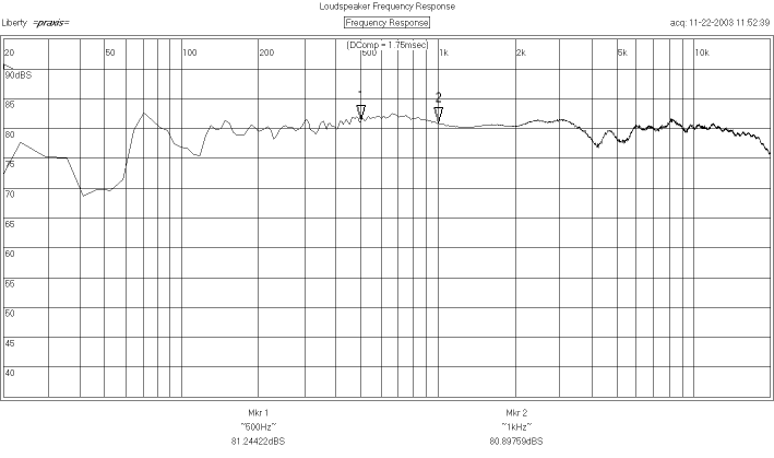
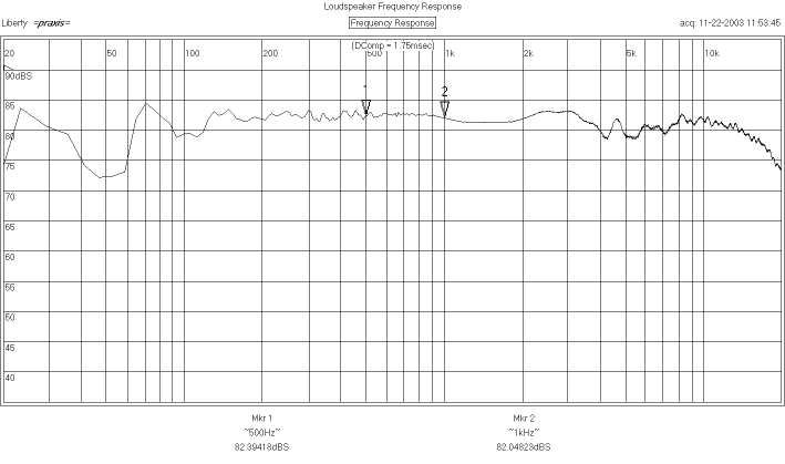
Here is the measured response at 30 degrees, 45 degrees, and 75 degrees off-axis horizontally. There are no serious irregularities other than the expected changes in diffraction effects and upper treble response.
30 degrees
45 degrees
75 degrees
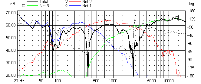
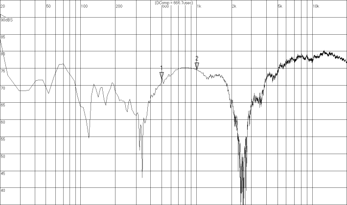
Here is the predicted on-axis response with the mid connected in direct polarity, which throws its response directly out of phase with the woofer and tweeter. It shows the intended crossover points of 350 Hz and 2500 Hz. This is followed by the measured reverse null at 1 meter. This is too short a distance to capture the nulls accurately in a 3-way design, but you get the idea.
Predicted Null
Measured Null
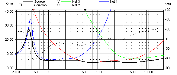
Predicted Impedance
Finally, here is the predicted impedance (which is accurate.) With the exception of the tuning frequency, the impedance varies narrowly between about 6 and 4 ohms.
Cabinet Details
The plans for the MBOW1 upper cabinet can be found here. These plans were meant originally for a larger tweeter than the OW1, so the routing and cutout will have to be adjusted for the smaller OW1 flange and inner diameter. You may also move the tweeter hole down a little so that the bottom of the OW1 flange is where the bottom of the original tweeter flange is indicated. In my prototype, I just used a rectangular 2 cu. ft. box for the bass cabinet, constructed with 3/4" mdf and a single shelf brace. The dimensions are 24 1/4" H, 12" W, 17.5" D. The woofer is mounted toward the top, with a center-to-center distance of 12" between the woofer and midrange. You will need some kind of isolation between the bass and upper cabinets. Simple rubber feet on the upper module will probably do. There really isn't room in the little upper cabinet for the entire Net 2 and Net 3 crossover. I would plan to mount the whole crossover in the bottom of the bass cabinet, or build a separate hollow base for all those components (some of which will be very bulky). The crossover will be very expensive if you use top-of-the-line poly caps. I used Axon poly caps for the larger values, and think they are a very good value (available from GR Research). Or I'm sure you could use mylar and probably never know the difference. I used a Sledgehammer steel laminate for the 4.0 mH woofer inductor (sold by Madisound).
If you wish to angle the sides of the bass cabinet in so that the top width equals the width of the upper cabinet (8 1/4"), mount the woofer as high as is feasible. The slightly greater center-to-center distance from the mid should not matter with a 350 Hz crossover. If anyone develops a single, integrated cabinet and likes the results, please e-mail me the plans.
Final Check List
Did you remember to wire the M130 with reverse polarity? Did you remember the 50 ohm bypass resistor around the first 1.0 mH series inductor in Net 2? If the sound is too bright for you, reduce the 20 ohm resistor in the Lpad to 15 ohm. You may also wish to increase the 2.0 ohm series resistor to 3.0 ohms.
| 
