|
Here is a revised crossover for my OkaraOW1 loudspeaker, which uses the Vifa P13 midwoofer and Hiquphon OW1 woofer housed in the cabinet originally designed for North Creek's OkaraII. The OkaraII uses the P13 with the ScanSpeak 9500 tweeter in an EBS box alignment. Ken Martinez asked me to substitute the OW1 tweeter and come up with a new crossover. Ken makes beautiful cabinets for either version of the OkaraII. I am not giving box dimensions or port tuning here, since I consider that information proprietary to North Creek. This is a kit you would build if you wanted to order cabinets from Ken, or already know how to build an OkaraII box.
This new version uses exactly the same topology as the original, but corrects for a defective microphone calibration file that produced a slightly rising response above 8 kHz. I am not sure everyone will prefer this version, since the original did have a very spacious, wide open sound, but this rendition is more accurate. The P13 woofer is happiest with a subwoofer, even with the EBS tuning used here.
On axis response:

Response at 15 degrees off axis horizontally:

Response at 45 degrees off axis -- note the superb dispersion of the OW1 tweeter:

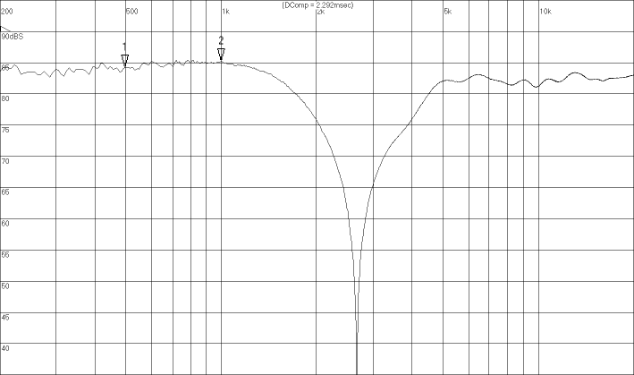
And here is the response with the tweeter connected with reverse polarity. It shows the crossover point of 2,800 Hz, and confirms that the woofer and tweeter are in phase around the crossover region when the tweeter is connected with direct polarity:

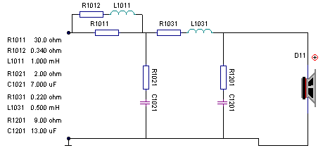
Here is the schematic for the woofer low pass filter. Those aren't really resistors in line with the inductors -- those values just represent the dcr of the inductors (which were Madisound Sidewinder 16 Ga air cores). But don't overlook the 30 ohm resistor that is in parallel with the first woofer coil. That resistor is very real and provides valuable frequency response shaping. Finally, the last rc shunt circuit is impedance compensation, so this is really a 3rd order electrical circuit. I would wire the impedance compensation directly across the woofer terminals to save space on what will be a very crowded board.

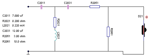
And here is the tweeter circuit:

|

